
 Preparation of Machine Control Files for GPS-Guided Construction Machinery
Trigon Survey & Investigation Ltd can prepare Machine Control Files (usually DXF) from conventional working drawings to interface with any of the three major satellite machine guidance systems in the UK (Leica, Trimble and Topcon).
As Land and Topographic Surveyors we are ideally experienced to undertake this work, as the process is essentially a reversal of that which goes to produce a land survey. The heavy machinery goes out and forms the ground surface to the profile within the “survey” model – in this instance, the engineers’ design!
What are Machine Control Data files?
The use of directly controlled (i.e driverless machines) in construction is increasing rapidly. The machines so controlled can include scrapers, dozers, excavators and regulators. The savings in time and cost over conventional methodologies (setting out pins, profile boards etc.) can be very considerable. There is also less likelihood of error.
The control systems employ GPS receivers that require coordinate string information in the form of “dxf” data files to Ordnance Survey Grid and Datum, so that the design “model” is shaped or excavated on the ground by the machines in question as they fix their position from satellites in space.
Trigon can prepare these critical control files, which is quite often a straightforward procedure normally taking place in two stages:
- Prestart information review
We start with a desk top review of all Architects’, Engineers’ and Subcontractor drawings and data.
Then, in conjunction with the main contractor, subcontractor and plant supplier, we devise a strategy for setting out the works and to guide machinery to a unified coordinate reference system (usually OSGB36 – UK Ordnance Survey’s National Grid ).
On large remediation or infrastructure projects, it is always useful to have a digital ground model (DGM) of the existing ground surface, either in 3d dxf formal or as a “csv” spreadsheet.
If this cannot be supplied, then we can undertake a fresh land survey on site to record the starting surface (using conventional topographical survey methods), from which the DGM can be created.
If the design has been prepared on the basis of a survey to an arbitrary local grid and datum, conversion of this to OS basis is quite often also a relatively straightforward procedure.
- Extraction of Data from design drawings
Following full information assembly and review, the required 3D coordinate strings are then created on electronic overlays of the designers’ CAD drawings within specialist ‘N4ce’ topographical survey software.
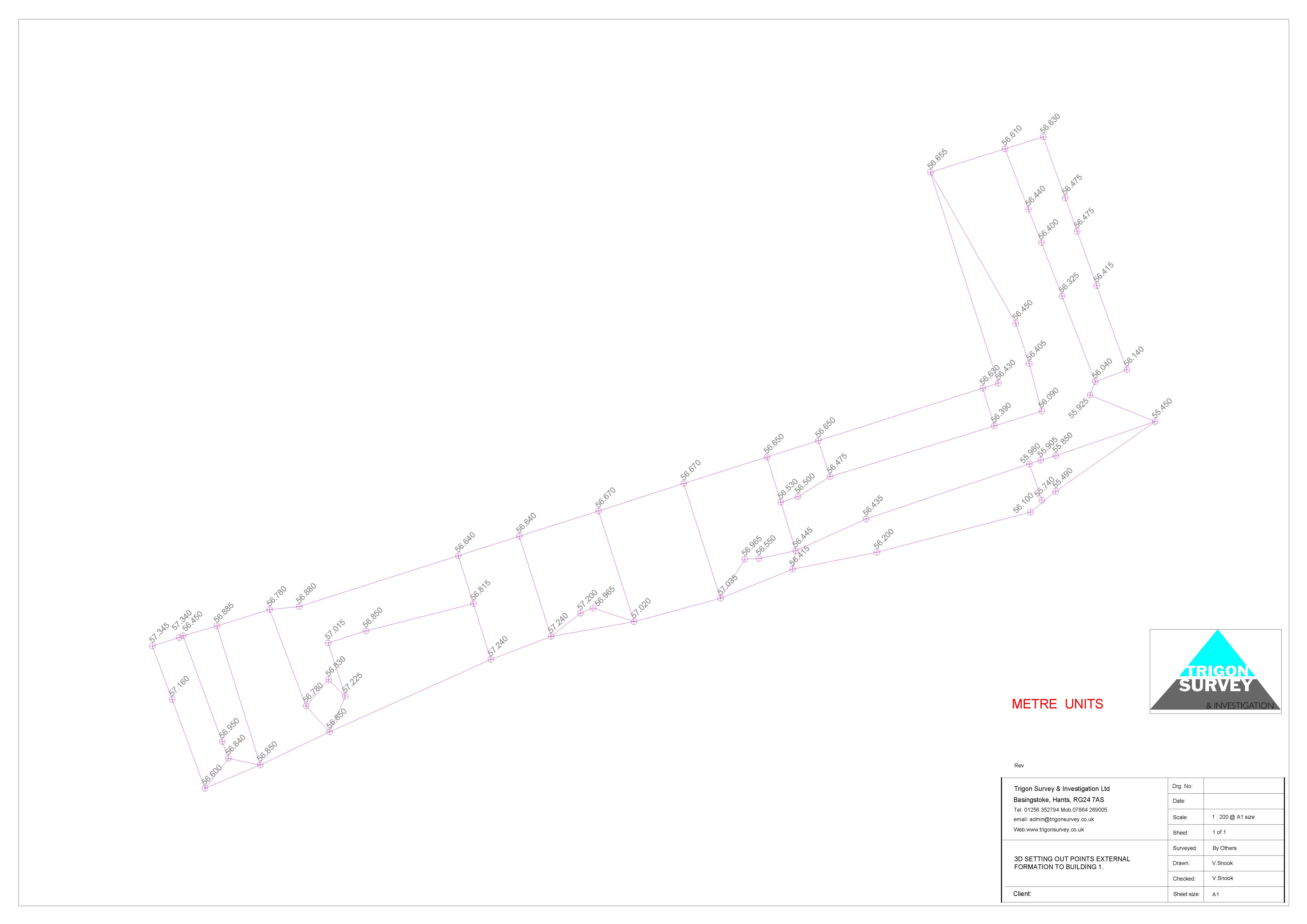
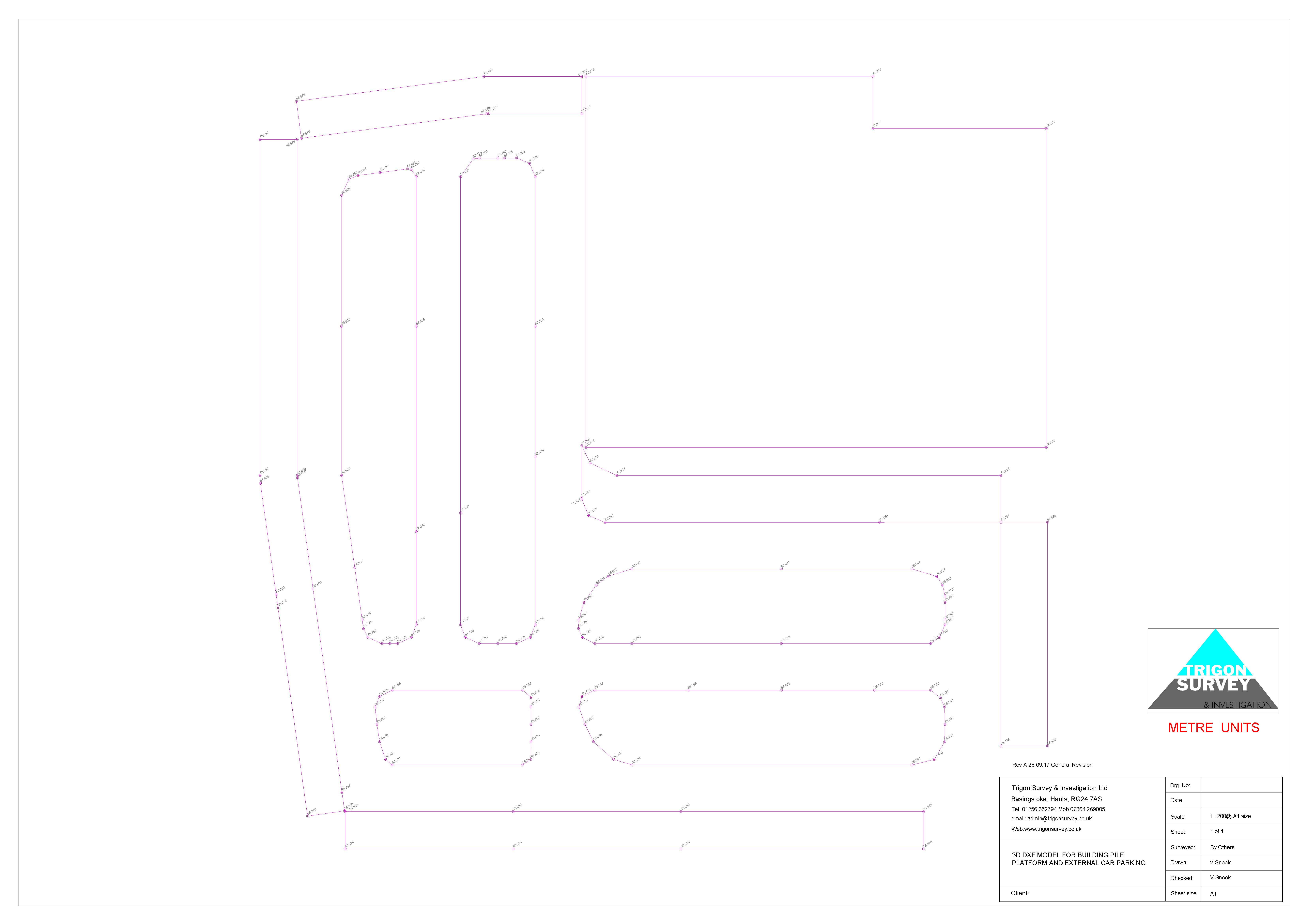
The overlays, when complete, are exported as new ‘dxf’ files in their own right for uploading into the relevant machine’s control system.
The dxf files can also be printed off as freestanding drawings (see pdf examples below), and excel data sheets will also be issued with the data files, combining to give unambiguous guidance to engineers and plant operators on the ground.
Click to open:

If needed, as-built topographical surveys can be undertaken to validate the process on completion of each stage.